Every foundation design begins with a question: how much load can the ground safely support?
Borehole investigations provide important information about soil conditions, but when engineers need direct verification of bearing capacity and settlement behavior at the foundation level, the Plate Load Test remains one of the most reliable field tests available.
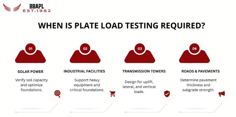
Used across industrial facilities, solar projects, transmission towers, roads, and commercial developments, the Plate Load Test provides measured ground response rather than theoretical assumptions.
A Plate Load Test is an in-situ field test conducted at the proposed foundation level to determine bearing capacity and settlement characteristics of soil. A rigid steel plate is placed on prepared ground, loaded incrementally through a hydraulic jack, and the resulting settlement is measured at each stage.
The output is a load-settlement curve, a direct record of how that specific soil responds to increasing load. From this curve, engineers extract:
Safe Bearing Capacity (SBC): The maximum pressure soil can carry without excessive settlement
Ultimate Bearing Capacity: The load at which soil shear failure occurs
Settlement characteristics: How much the foundation will move under service loads
Modulus of Subgrade Reaction: Used for raft foundation and industrial floor slab design
Most references to IS 1888 stop at naming it. Here is what the standard actually specifies, because the details matter for result validity.
| Requirement | Specification |
|---|---|
| Plate dimensions | The standard permits square or circular plates ranging from 300 mm to 750 mm. Plate thickness must be sufficient to ensure rigidity, typically 25 mm minimum for steel. For soft soils or where scale effects are a concern, larger plates are preferred. |
| Test pit depth | The pit must be excavated to the proposed foundation level. Testing at any other depth produces results that do not represent design conditions. |
| Load increments | Load is applied in stages, each increment equal to approximately one-fifth of the estimated safe bearing capacity, or 50 kN/m², whichever is smaller. Rushing this compromises the curve. |
| Settlement stabilization criteria | Each load stage is maintained until the rate of settlement reduces to 0.02 mm per hour, or for a minimum of one hour, whichever comes first. Removing the load before stabilization produces an artificially stiff curve. |
| Number of dial gauges | Minimum two dial gauges, placed diametrically opposite, to detect and account for tilting. |
| Unloading and rebound | After the maximum load is reached, the test is unloaded in stages, and rebound readings are recorded. This data informs elastic recovery characteristics and is particularly relevant for pavement subgrade and raft design. |
| Step | Procedure |
|---|---|
| Step 1: Excavation | A test pit is excavated to the proposed foundation depth. The pit dimensions must be large enough to eliminate boundary effects that could influence the results. |
| Step 2: Surface Preparation | The exposed soil surface is cleaned and levelled carefully. A thin layer of fine sand may be used to achieve uniform contact between the steel plate and the ground. The soil should not be disturbed or compacted during this process. |
| Step 3: Installation of Test Equipment | The steel plate is placed at the centre of the prepared surface. A hydraulic jack is positioned between the plate and a suitable reaction system such as kentledge loading or an anchored reaction frame. |
| Step 4: Incremental Loading | The load is applied gradually in predetermined increments. Each load stage is maintained until the settlement stabilisation criteria specified in IS 1888 are satisfied. |
| Step 5: Settlement Recording | Settlement readings are typically taken at intervals of 1, 2, 5, 10, 20, 30, and 60 minutes after applying each load increment. Both dial gauges are monitored simultaneously to ensure consistency. |
| Step 6: Continue Loading | Loading continues until a clear failure pattern develops or until the specified settlement limit is reached. For most foundation investigations, loading proceeds until approximately 25 mm of settlement is observed. |
| Step 7: Unloading | The load is removed in stages equal to the loading increments, and rebound measurements are recorded throughout the unloading process. |
The load-settlement curve is plotted with applied pressure on the X-axis and settlement on the Y-axis. Three failure patterns are possible depending on soil type: general shear failure, local shear failure, and punching shear failure.
For dense sands and stiff clays, the curve shows a distinct failure point, a sharp inflection where settlement accelerates without an increase in load. Ultimate bearing capacity is read directly from this point.
For loose sands and soft clays, failure is gradual. Ultimate capacity is taken at the point where the tangent to the curve makes 45° with the settlement axis, or by the log-log method.
Safe Bearing Capacity is the lower of:
• Ultimate bearing capacity divided by a factor of safety (typically 2.5 to 3)
• The load corresponding to a settlement of 25 mm (for most structures)
Extrapolating plate results to actual footing size requires the IS 6403 and standard correlation equations. For sandy soils, Terzaghi’s scaling relationship applies: the settlement of a footing increases with footing width relative to plate width. For clays, bearing capacity scales approximately linearly with footing width. Applying plate results directly to full-scale footings without this correction is one of the most common misinterpretations in practice.
A Plate Load Test provides valuable information about bearing capacity and settlement behaviour, but incorrect interpretation can lead to unsafe foundation designs or overly conservative construction costs. Some of the most common mistakes include:
| Common Mistake | Impact |
|---|---|
| Testing Above the Actual Foundation Level | IS 1888 requires the test to be conducted at the proposed foundation depth. Conducting the test at a shallower level may produce higher bearing capacity values that do not represent the soil conditions supporting the structure. The resulting foundation design can therefore be unconservative. |
| Using Plate Results Directly for Footing Design | The behaviour of a 300 mm to 750 mm test plate is not identical to that of a full-scale footing. Plate Load Test results must be corrected using accepted correlations and scaling relationships before being applied to actual foundation dimensions. Ignoring this step is one of the most common design errors. |
| Ignoring Settlement Criteria | Many engineers focus only on Safe Bearing Capacity and overlook settlement performance. A foundation may satisfy bearing capacity requirements yet still experience excessive settlement that affects structural performance. Both criteria must be evaluated together. |
| Stopping the Test Before Settlement Stabilization | Each load increment should be maintained until the settlement stabilization requirements specified in IS 1888 are achieved. Terminating the test too early often produces an artificially stiff load-settlement curve and can overestimate soil performance. |
| Relying on a Single Test Location for Large Sites | Soil conditions can vary significantly across industrial plants, solar parks, transmission corridors, and infrastructure projects. A single Plate Load Test may not represent the entire site. Multiple tests or supplementary geotechnical investigations are often required where soil variability is expected. |
Engineering judgment is as important as the test itself. A Plate Load Test provides reliable data only when it is conducted correctly, interpreted appropriately, and correlated with the overall geotechnical investigation findings.
Plate Load Testing is particularly valuable for projects where foundation performance has a direct impact on safety, durability, and construction costs.
| Project Type | Why Plate Load Testing Is Important |
|---|---|
| Solar Power Projects | Large solar installations can have thousands of foundation points. PLT helps verify soil capacity, optimize foundation design, and avoid unnecessary concrete usage. |
| Industrial Facilities | Equipment foundations, crane girders, storage tanks, and machine bases require accurate Safe Bearing Capacity (SBC) values to ensure long-term stability and compliance with engineering requirements. |
| Transmission Towers | These structures are exposed to vertical, uplift, and lateral loads. PLT data supports the design of safe and reliable foundation systems. |
| Roads and Pavements | The test provides the Modulus of Subgrade Reaction, an important parameter used to determine pavement thickness and improve cost efficiency. |
| Method | What It Measures | Depth Coverage | Best Use |
|---|---|---|---|
| Plate Load Test | Direct bearing capacity and settlement | Shallow (2–3× plate width) | Foundation level verification |
| SPT (IS 2131) | Soil resistance to penetration | Full borehole depth | Stratigraphic profiling |
| Laboratory Testing | Index properties, shear strength | Sample-dependent | Design parameter derivation |
| CPT | Continuous resistance profile | Full depth | Layered soil characterization |
The Plate Load Test is the only method that measures the actual load-settlement response. It does not replace borehole investigation, it validates and refines what the borehole suggests. A complete geotechnical engineering services program uses both.
A PLT report is only as credible as the laboratory issuing it. NABL accreditation under ISO/IEC 17025:2017 means that BBAPL’s testing procedures, equipment calibration, measurement uncertainty, and reporting formats are independently audited against international standards.
For projects requiring CPWD, PWD, or institutional approvals, an NABL-accredited testing lab report carries authority that non-accredited reports do not. This matters at the tender stage, during third-party review, and when disputes arise.
Bhargava Building Atelier Pvt Ltd is CPWD empanelled, NABL accredited, and has conducted geotechnical engineering services for DRDO, SBI, MP Housing Board, and private sector clients, including Godrej and CG Power, since 1982.
A Plate Load Test conducted correctly, per IS 1888:1982, by a NABL accredited testing lab, gives foundation designers the one thing that no desk study can provide: measured ground behavior at the actual foundation level.
For industrial, solar, infrastructure, or commercial projects where foundation cost and risk both matter, this test belongs in your investigation program.
A Plate Load Test is more than a code requirement. It is a direct verification of how soil will behave under real foundation loads. When combined with borehole investigations and laboratory testing, it provides engineers with the information needed to design safe, economical, and reliable foundations.
Whether the project involves solar infrastructure, industrial facilities, transmission towers, roads, or commercial developments, accurate bearing capacity and settlement data help reduce risk, improve design confidence, and avoid costly foundation-related problems during construction and operation.
A Plate Load Test is an in-situ field test conducted at the foundation level to directly measure soil bearing capacity and settlement characteristics under incremental loading.
IS 1888:1982 is the primary Indian Standard for Plate Load Testing. IS 6403 is used alongside it for bearing capacity determination of shallow foundations.
Safe Bearing Capacity is the maximum pressure soil can sustain without excessive settlement or failure. It is derived from the load-settlement curve by applying a factor of safety of 2.5 to 3 on ultimate bearing capacity.
IS 1888:1982 permits rigid steel plates between 300 mm and 750 mm, square or circular, with minimum 25 mm thickness to ensure rigidity during testing.
SPT measures soil resistance to penetration across depth and is used for stratigraphic profiling. A Plate Load Test directly measures load-settlement response at foundation level, SPT estimates it indirectly.
It is not universally mandatory but is strongly recommended for industrial facilities, solar projects, bridges, transmission towers, and any structure where foundation loads are significant or soil conditions are uncertain.
Yes, but the pit must be dewatered before testing and water level maintained below the plate during the test. Results from inadequately dewatered pits are unreliable.
There is no fixed number prescribed by IS code. Test frequency depends on site variability, project area, and foundation type. For utility-scale solar, one test per distinct soil zone is a common minimum.
A NABL accredited testing lab report is independently audited for equipment calibration, procedure compliance, and measurement accuracy. It carries greater acceptance with CPWD, PWD, and institutional approvers than non-accredited reports.
It is the ratio of applied pressure to settlement, derived from PLT results. It is used in the design of raft foundations, industrial floor slabs, and road pavement layers to assess soil stiffness under distributed loads.


Talk to Our Experts Today — We're just a call or message away.

Already a member? Sign in now